The EasyVR Commander software can be used to easily configure your EasyVR module connected to your PC through a QuickUSB cable, an adapter board, or by using the microcontroller host board with the provided “bridge” program (available for ROBONOVA controller board, Arduino, Parallax Basic Stamp).
You can define groups of commands or passwords and generate a basic code template to handle them. It is required to edit the generated code to implement the application logic, but the template contains all the functions or subroutines to handle the speech recognition tasks.
Getting Started
Connect the QuickUSB cable, an adapter board or a microcontroller host board with a running “bridge” program6 to your PC, then check that all devices are properly turned on and start the EasyVR Commander.
Select the serial port to use from the toolbar or the “File” menu, and then go with the “Connect” command.
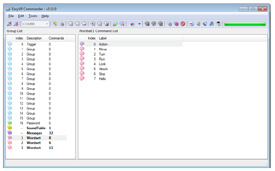
Figure 3 – Main application window
There are five kinds of commands in the software (see Figure 3 and Figure 7):
- Trigger – special group where you have the built-in SI trigger word “Robot” and you may add one
user-defined SD trigger word. Trigger words are used to start the recognition process
- Group – where you may add user-defined SD commands, organized in subsets
- Password – special group of “voice passwords” (up to 5), using Speaker Verification (SV) technology
- Wordset – built-in set of SI commands (for instance in Figure 3 above, the Wordset 1 is selected)
- Grammar – custom set of SI commands (created with QuickT2SITM Lite software).
There are also two other categories of data shown:
- SoundTable – list of compressed audio samples (prompts, sounds, etc.) loaded into the module
- Messages – run-time sound recordings stored on internal memory
Remote Connections (Advanced Topic)
The EasyVR Commander can also connect to remote systems, typically Linux PCs or Linux embedded systems (such as BeagleBone, Raspberry Pi, etc.), that expose a remote EasyVR module through the network.
To enable this feature (available since v3.12.0) you need to configure the remote system and manually edit the EasyVR Commander settings.
On Linux based systems, you can use either “socat” or “ser2net” utilities to map the serial port where the EasyVR module is physically connected to a TCP port of your choice.
Attention! The examples below have been tested with specific versions of the hardware and the software; they might not work for your own combination. Since modifications to the system configuration are required, this topic is recommended for expert users only!
Configuring the Remote System
Example 1: BeagleBone Black (Rev C)
- Connect the EasyVR 3 module to UART1 on the BeagleBone expansion headers:
| EasyVR 3 Module | BeagleBone Black |
| GND | DGND (P9.1) |
| 5V or 3V3 (depending on PWR jumper) | VDD_3V3 (P9.3) |
| TX | UART1_RXD (P9.26) |
| RX | UART1_TXD (P9.24) |
In alternative, you may use an adapter board for mikroBUS interface, like the “mikroBUS Cape” by
MikroElektronika, just make sure you set the PWR jumper to the +3V3 position on the EasyVR 3
module and that you plug it in socket 2 or 3 (other sockets use a different UART).
- Install a recent Debian image (e.g. Jessie) on the SD Card or internal e-MMC memory
- Run the following commands on a shell prompt (comments start with #):
# install ser2net
sudo apt-get install ser2net
# permanently map TCP port 6666 to UART1
echo 6666:raw:0:/dev/ttyO1:9600 8DATABITS NONE 1STOPBIT | sudo tee -a /etc/ser2net.conf
# enable UART1 pin mux
echo cape_enable=bone_capemgr.enable_partno=BB-UART1 | sudo tee –a /boot/uEnv.txt
# reboot
sudo reboot
Example 2: Raspberry Pi Model B+
• Connect the EasyVR 3 module to the Raspberry Pi expansion header:
| EasyVR 3 Module | Raspberry Pi |
| GND | DGND (Pin 9) |
| 5V or 3V3 (depending on PWR jumper) | 3.3V (Pin 1) |
| TX | UART_RX (Pin 10) |
| RX | UART_TX (Pin 8) |
In alternative, you may use an adapter board for mikroBUS interface, like the “PI2 click Shield” by MikroElektronika, just make sure you set the PWR jumper to the +3V3 position on the EasyVR 3 module.
- Install a recent Debian image (e.g. Jessie) on the SD Card or internal e-MMC memory
- Run the following commands on a shell prompt (comments start with #):
# install ser2net (and samba to broadcast hostname)
sudo apt-get install ser2net samba
# permanently map TCP port 5555 to UART
echo 5555:raw:0:/dev/serial0:9600 8DATABITS NONE 1STOPBIT | sudo tee -a /etc/ser2net.conf
# enable serial interface without login shell (menu Interfacing Options > Serial > No > Yes)
sudo raspi-config
# reboot
sudo reboot
Configuring the EasyVR Commander
- Locate the folder where the EasyVR Commander settings are stored. Open any Explorer folder, copy-paste this text in the address bar and press Enter:
%LocalAppData%\VeeaR\EasyVR Commander
- Open the file “Settings.ini” and append the following section at the end:
[AddressList]
Count=2
Address0=TCP:raspberrypi,5555
Address1=TCP:beaglebone,6666
Those lines reflect the above examples of remote systems configuration and expect that your PC and the remote systems are on the same local network or anyway that the remote systems can be reached via TCP connection to the specified symbolic addresses (numerical IP addresses are also supported).
- Restart the EasyVR Commander for the new settings to become effective. Now you can choose to
connect to one of the remote systems you just added, as if they were regular serial ports.
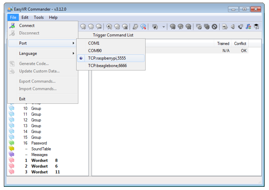
Figure 4 – Remote connections now available
Speech Recognition
The recognition function of the EasyVR works on a single group at a time, so that users need to group together all the commands that they want to be able to use at the same time.
When EasyVR Commander connects to the module, it reads back all the user-defined commands and groups, which are stored into the EasyVR module non volatile memory.
You can add a new command by first selecting the group in which the command needs to be created and then using the toolbar icons or the “Edit” menu.
A command should be given a label and then it should be trained twice with the user’s voice: the user will be guided throughout this process (see Figure 5) when the “Train Command” action is invoked.
Note: Only Latin characters and digits can be used for labels, as well as the underscore character.
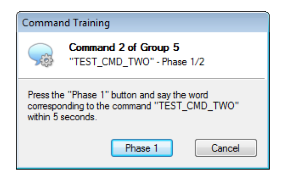
Figure 5 – Guided training dialog
After clicking on “Phase 1” or “Phase 2” buttons, remember you have to start speaking only when you see this little window:

If any error happens, command training will be cancelled. Errors may happen when the user’s voice is not heard correctly, there is too much background noise or when the second word heard is too different from the first one.
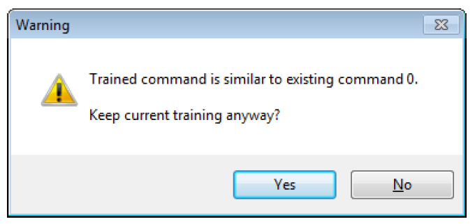
Figure 6 – Alert dialog in case of training conflicts
The software will also alert if a command is too similar to an existing one by specifying the index of the conflicting command in the “Conflict” column. For example, in the following Figure 7 the command “TEST_CMD_ONE” sounds too similar to “TEST_CMD_ZERO” (i.e. they have been trained with a similar pronunciation).
Note: TEST_CMD_ZERO and TEST_CMD_ONE are just examples of labels, you should use label names that reflects the real command that you are going to train.
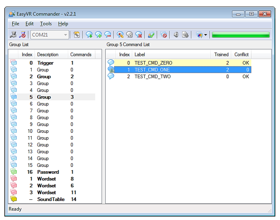
Figure 7 – Showing conflicting commands
The current status is displayed in the EasyVR Commander list-view where groups that already contain commands are highlighted in bold.
The selected group of commands can also be tested, by using the icon on the toolbar or the “Tools” menu, to make sure the trained commands can be recognized successfully.
Note: If you want to re-train a command you need to erase the previous training first.
Note: “Vocal passwords” (Group 16) are much more sensitive to environmental noise and distance from the microphone: be sure to train and to verify the password in similar conditions.
Recognition Settings
The module comes programmed with some default settings that can affect voice recognition. These parameters can be altered in those cases where the default values do not offer the best performance.
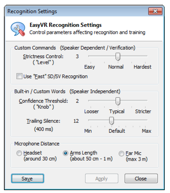
Figure 8 – Interface for changing recognition settings
The “Level” and “Knob” parameters affect the way recognition results are evaluated and reported, each one for a different kind of voice recognition algorithm (Speaker Dependent/Verification and Speaker Independent, respectively).
Both these values are used for a sort of acceptance threshold: each word or command recognized is assigned a score by the algorithm, which is compared to the threshold.
In some situations the algorithm may flag a correct result as an error or a low confidence result. In those cases you may try to lower the threshold and allow more results to be reported as correct. The drawback is that even words that were correctly refused before now might also be accepted.
The vice-versa is also true: you can increase the threshold to avoid some incorrect words to be reported as good, but then you may also lose a few correct results. So, in the end, you need to find the best compromise.
Ticking “Use “Fast” SD/SV Recognition” will use a faster algorithm for SD and SV recognition. In a similar way, faster SI recognition can be obtained by lowering the Trailing Silence (default is 400 ms).
The last parameter affects the internal microphone pre-amplifier and AGC (Automatic Gain Control) stages and is an indication of the expected operating distance of the microphone from the speaker’s mouth.
Note: The EasyVR module is optimized for the default distance setting “Arms Length”. Any other settings may require hardware modifications to the on-board gain resistor.
To change the recognition settings of the currently connected EasyVR device press the “Apply” button.
The window is non-modal, so you can test the effects of your changes while leaving it open.
The “Save” button makes the EasyVR Commander remember your settings and automatically apply them to every connected device. The module itself does not store any option.
Phone Tones Generation (DTMF)
The EasyVR module is also capable of generating DTMF sounds. This feature can be tested by using the “Dial Tones” command in the “Tools” menu.
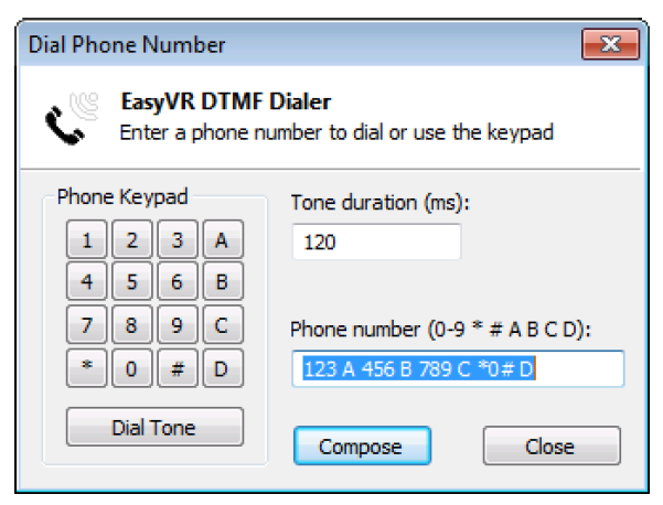
Figure 6 – Interface for generating phone tones
The tone duration can be specified in increments of 40 ms (milliseconds). The dial tone has a fixed duration of 3 seconds (its duration can be modified when programming the EasyVR).
Testing SonicNetTM
The EasyVR module is also capable of generating DTMF sounds. This feature can be tested by using the “Dial Tones” command in the “Tools” menu.
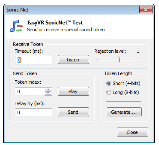
Figure 7 – Interface for testing SonicNet features
The EasyVR module can listen for incoming tokens continuously, or for as long as about 28 seconds (specified with a granularity of around 27.5 ms). Another parameter for token detection is the rejection level that specifies the receiver sensitivity: higher rejection means lower sensitivity that is a lower detection rate, and vice-versa.
When the timeout parameter is set to 0, the module will listen continuously and you can use the “Play” button to send a token from your PC soundcard and the “Stop” button to stop listening.
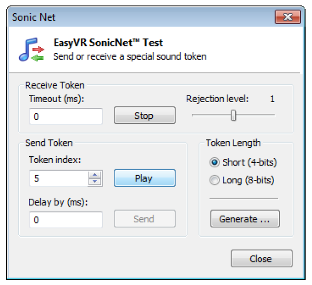
Figure 9 – Modified interface during continuous listening
A pop-up window will display the current state of token detection:

Tokens may also be transmitted from the module with the “Send” button. An optional delay parameter can be used to indicate that the token will be mixed with the next sound played from the Soundtable, after the specified amount of time since the playback begins. In this case the SonicNet dialog will close to let you choose a sound to play back.
Note: If you want to mix tokens with a compressed audio sample, you must use a compression scheme with a sample rate of 9.3 kHz when building the Soundtable in the QuickSynthesisTM tool.
If the delay is 0, the token is sent out immediately. Other values can be specified up to around 28 seconds of delay (with a granularity of around 27.5 ms).
Finally, you can also export all the tokens of the specified length to some folder on your PC as Wave files (.WAV format) by using the “Generate…” button. You can then use those files to embed SonicNetTM tokens into other software or external sound sources (such as portable players, CDs or DVDs, etc…)
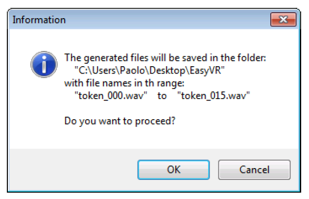
Figure 10 – Export of 4-bit tokens
Real-Time Lip-Sync
Another feature available from the “Tools” menu is the “Real-Time Lip-Sync”. In fact, starting from Firmware revision 4, you can use this feature to let your “animatronic” characters “speak” moving their lips. Clicking on “Real-Time Lip-Sync” will open the following window:
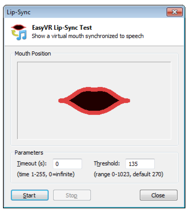
Figure 11 – Lip-Sync interface with animated mouth
If you click on “Start” the virtual mouth on the window will start moving in sync with your voice. In real animatronic characters you can use a servo to move their lips.
You can specify a maximum duration (timeout) or leave it running until you click on “Stop”. You may also specify a threshold for the input signal power, below which the mouth is considered closed (silence).
Import and Export of Custom Commands
Starting with firmware revision 4 of the EasyVR 3 module, it is possible to export all the data, including training, of the existing commands and passwords into a file. You can then use that file to import all the commands at once into another module or just as a backup for your commands.
While the module is connected, click on “Export Commands…” under the “File” menu and write the name of the file that will contain the exported commands. In the same way you can select “Import Commands…” and then choose the file with the commands you would like to import.
Note: During the Import procedure all the existing commands will be discarded and replaced by the ones contained in the specified file!
During the Import/Export process some feedback is provided with pop-up windows and with the progress bar on the main window.
Using Custom Data
Sound Table
The EasyVR module can play one of the sounds or sentences saved on its internal flash memory. A predefined “beep” sound is also always available, even when no sounds have been downloaded to the module.
The custom sounds are organized in a so-called “sound table” that users can prepare and build with the special QuickSynthesisTM tool. Please refer to this application’s own manual for details about the creation of a sound table. Let’s summarize the basic steps here:
- Prepare the audio files you want to include in the sound table in WAV format, uncompressed 16-bit 22050Hz mono. To create the sound files you may use a free software like Audacity for example (http://audacity.sf.net)
- Open Sensory’s QuickSynthesisTM 5 and create a new project, specifying “RSC4 family”
- Add your WAV files and specify one of the supported compression scheme (see table below)
- Optionally add sentences, by combining basic WAV sounds. That allows you to save memory when you have speech audio files, if they share some pieces (like “You said” + “One”, “You said” + “Two”, and so on)
- Build the project with QuickSynthesisTM and use default settings (“Build linkable module”, “Load in CONST space”, “Load above or at: 0”). You will be asked to recompress new or modified sound files, just confirm and proceed
- Now save your project and build it once again, so that the EasyVR Commander will see that your build is up to date.
The audio compression formats supported by the EasyVR module (from highest to lowest compression rate):
| Compression Scheme | Available Time (8kHz 15% silence) | Available Time (9.3kHz 15% silence) |
| SX-2 | 20.9 minutes | 18.1 minutes |
| SX-3 | 18.4 minutes | 15.9 minutes |
| SX-4 | 16.3 minutes | 14.1 minutes |
| SX-5 | 14.7 minutes | 12.6 minutes |
| SX-6 | 13.4 minutes | 11.6 minutes |
| 4-bit ADPCM | 209 seconds | N/A |
| 8-bit PCM | 108 seconds | 92 seconds |
For audio file containing speech, the SX-3 compression is usually a good choice. If you need higher quality try lower compression rates. Please note that due to the sampling rate used, the audio files cannot contain very high frequencies (less than half the sampling rate).
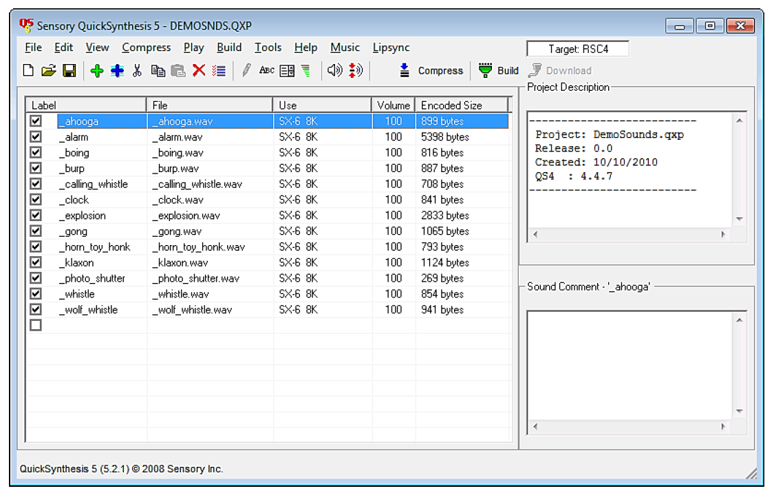
Figure 12 – External tool for creating a Soundtable
Note: Only one Soundtable can be downloaded to the EasyVR module, so make sure you include all the sounds you want to use in a single project.
Speaker Independent Custom Vocabularies
The set of built-in Speaker Independent recognition vocabularies can be expanded with custom grammars, that you can create with the QuickT2SITM tool (a separate license is required to use the software).
When you create a QuickT2SITM project, you are presented with a list of words or short phrases (also called “commands”) and an optional trigger word/phrase. The so-called “trigger” is a special set that contains only one word or phrase, with an improved recognition performance, that is used as an entry point for any vocal interaction with a device that is continuously listening to the user’s voice.
If you need to use a trigger word, it is important to carefully choose it so that it has good performance, with very few unintended activations and a high recognition rate. When the user says the trigger word followed by a command, the system can discard unintended activations when the trigger is not followed by a command within a short amount of time (usually around 3 seconds). Moreover, there is only one trigger word to listen to, instead of a list of several commands, so the chance to pick up a random command from background noise or talk is also lower, when using a trigger word.
For assistance on using the QuickT2SI™ Software, please refer to the software help file.
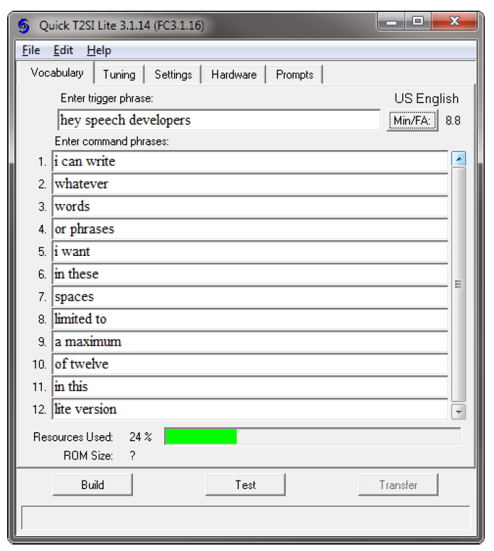
Figure 13 – External tool for custom vocabularies
Several projects can also be combined together if they are using the same acoustic model (language data) using the Acoustic Model Combiner included with the tool. This is useful if you have many command vocabularies, in order to save space in the EasyVR memory.
Updating Custom Data
Once the sound table and/or custom recognition grammars have been created, they can be processed by the EasyVR Commander and downloaded to the module. Note that you must first disconnect from the module and do the steps required to start it in “boot-mode” (see the section Flash Update).
Now the command “Update Custom Data” is enabled, either on the toolbar or the “File” menu, and it can be used to start the update process. First you are required to list all the QuickSynthesisTM and QuickT2SITM projects you want to use. A new file containing the specified custom data will be generated and the contents will be displayed, so that you can verify them before updating the module.
Note: The projects must have been built already with the QuickSynthesisTM or the QuickT2SITM tool, before the custom data generation can be completed successfully. If a recent build is not available you will receive a warning message, the project files can be opened in their respective tools and a fresh build started (make sure the project file has been saved before the build).
Once back in the EasyVR Commander the project can be reloaded by pressing the “Refresh” button. If the process completes successfully, the “Download” button will be enabled and the flash update process can start.
The default format of generated data is suitable for the EasyVR 3. For previous versions of the module or the shield please make sure to check the option “Old Format (EasyVR 2.0)”.
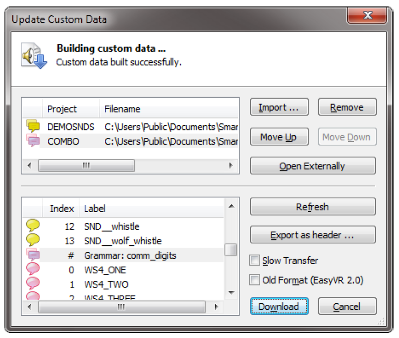
Figure 14 – Interface to build and download custom data
The download process will connect at a higher speed to the EasyVR module, so the “bridge” program running on your host device might not work (in particular Robonova and Basic Stamp cannot be used for this purpose) and you might need a true “serial adapter”.
The full speed used is 230400 bps, but the option “Slow transfer” can be used to reduce it to 115200, for better compatibility with slower serial adapters7. One adapter that can go to full speed is the QuickUSB cable. Otherwise any USB/Serial adapter with TTL/CMOS interface can be used for updating the flash. The
EasyVR Shield can be used for the download, provided that the mode jumper is in UP or LEO position.
Note: Every download will overwrite the previously transferred custom data.
After the download completes, a new connection can be established with the EasyVR module (in “normalmode”) and the new sounds will be displayed by the EasyVR Commander, in the special group “SoundTable” (the last one in the list with a yellow icon). They can be played back and tested using the “Play Sound” command on the toolbar or in the “Tools” menu. See also how to do that in your application in the code example Use custom sound playback.
Custom grammars will be displayed just after the built-in word sets and they work exactly the same way. Trigger words, when specified, will have their own vocabulary with only one entry. You can test and use the custom trigger and command grammars as you do with the built-in ones.
Note: The built-in trigger word set is handled in a special way, as it is active also when recognizing from the first user defined command group. This is the only case where SD and SI commands are mixed together and does not apply to custom trigger vocabularies.
Message Recording
Starting from firmware Revision 1 of the EasyVR 3 module, it’s possible to record up to 32 messages. The communication protocol and Arduino library have been updated accordingly (see related chapters).
The first time you update the module with a firmware with message recording capability, the serial flash memory of the module has to be formatted. The EasyVR Commander will automatically identify a module with the memory to be formatted and will alert you with the following window:
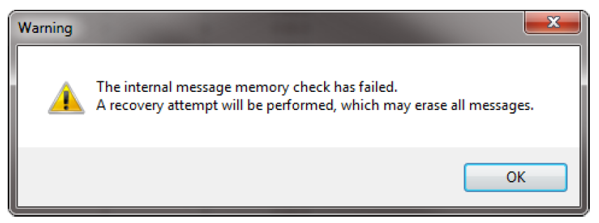
Figure 15 – Alert for corrupted message storage
The same window could appear in case the memory is corrupted for any reason (i.e. the module has been switched off while recording or erasing a message).
With EasyVR Commander v3.10.0 and above you can also record, play and erase messages by clicking on the specific buttons, after selecting the “Messages” group in the Group List.
In order to record a message you have to press the “record button” to start recording and press it again to stop.
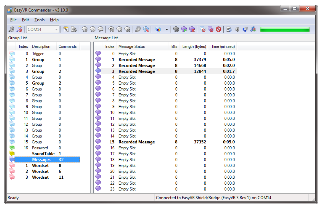
Figure 16 – User interface for messages
Updating Firmware
The EasyVR firmware can be updated in a similar way to custom data by using the command “Update Firmware…” from the “Help” menu. Note that you must first disconnect from the module and do the steps required to start it in “boot-mode” (see the section Flash Update).
Firmware files can be found in the EasyVR Commander installation folder (default C:\Program Files (x86)\VeeaR\EasyVR Commander), for instance file “EasyVR3_FW_Rev0.EVRFW” is the EasyVR 3 firmware Revision 0.
Please be sure to get the most up-to-date EasyVR Commander in order to have to most up-to-date available firmware as well.
The specified file will be verified as an official firmware release and basic version information will be displayed. If the firmware passes the verification step, then the “Download” button will be enabled.
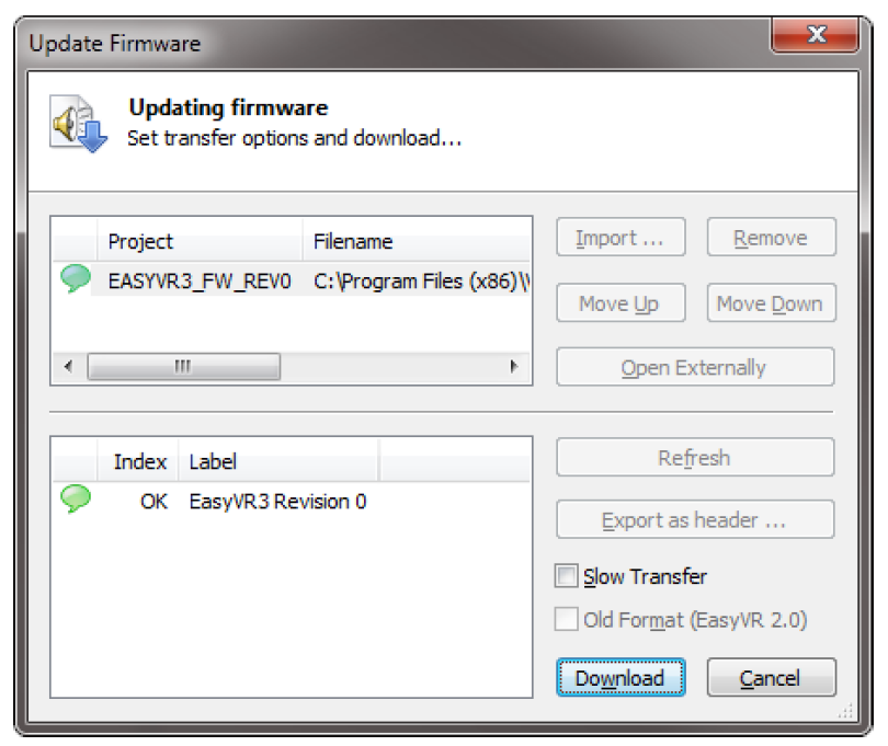
Figure 17 – Interface for updating EasyVR firmware
Note: After a new firmware is downloaded to the module, the custom data already present (sound table and grammars) is erased and it must be downloaded again if necessary.
Important Upgrade Notice
Since EasyVR 3 Firmware Revision 5 the internal memory layout for user data has changed, in order to accommodate space for 32 more SD commands, increasing the total maximum number of commands to 64.
The space previously reserved for live message recordings has therefore been reduced by around 20%.
When upgrading firmware to Revision 5 or later (and also if going back to a previous version) you should follow these steps:
- Use the “Export Commands” function to save a backup of your SD/SV commands (optional);
- Erase all data from user memory, with the “Reset All” command (all the recorded messages and user commands will be deleted);
- Perform the firmware upgrade to Revision 5;
- Use the “Import Commands” feature to restore commands from the previous backup (optional).
