Assembly notes
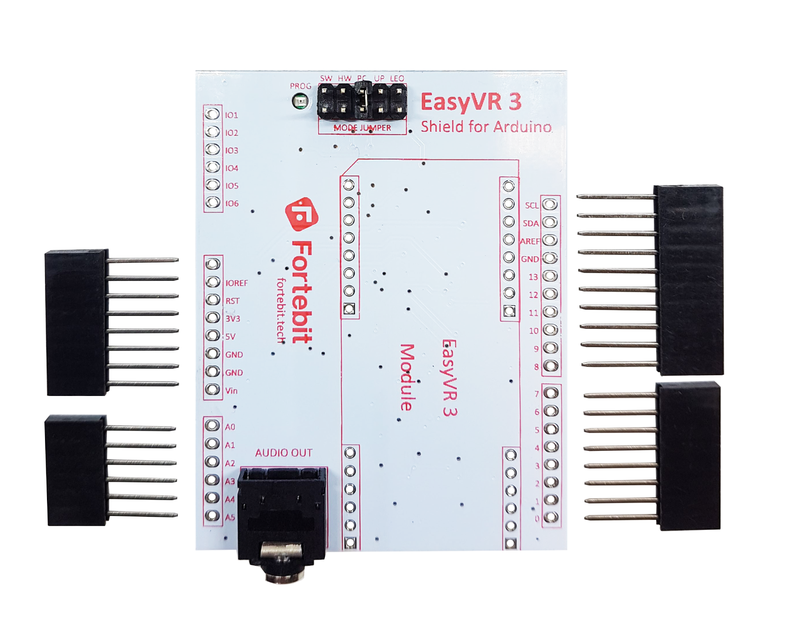
The EasyVR Shield 3 is provided with separate through-hole headers to connect the Shield to Arduino boards and other microcontroller-based boards adopting an Arduino compatible interface.
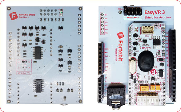
The EasyVR 3 module is provided separately and it should be fully assembled before it is soldered on top of the Shield. Make sure they are both well soldered in order to prevent electrical issues (see highlighted areas in the picture below).
Some practical guides to hand soldering:

Before you mount the EasyVR 3 module on the top, make sure you have assembled the pass-through headers on the EasyVR Shield 3 in the correct position and orientation. It is easier if you place all the connectors through the Shield with their plastic housings faced down on your desk, so that they can stand straight and vertical, and allow soldering of the metal leads easily from the back side of the board, which is now facing up.
As the last step, insert an already assembled EasyVR 3 module on its reserved footprint on the Shield, make sure it is plugged all the way in, and then complete soldering of male headers on the bottom side.
The end result should be similar to the following pictures:

Note: Pay attention to the tail of male headers (red areas) on the bottom of the EasyVR 3 module when you plug the Shield on a base board and make sure they are not touching other metal parts or connectors. If necessary you can trim the tails to prevent undesired contacts.
Prepare the software
- Install the EasyVR Commander, available on the VeeaR website:
http://www.veear.eu/downloads/ - Install a recent version of the Arduino IDE, available from the official Arduino community:
https://www.arduino.cc/en/main/software - Install the EasyVR Arduino libraries[1] on your PC.
You can use the “Library Manager” in recent versions of the Arduino IDE to automatically download and install the latest version of the library.
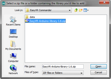
In alternative, to perform a manual install see:
https://www.arduino.cc/en/Guide/Libraries

Figure 1 – Manual installation of Arduino library
Prepare the hardware
- Insert the EasyVR Shield on top of your Arduino board
- If you want audio output, either wire an 8Ω speaker into the SPEAKER connector (J5) on the EasyVR module or connect headphones or amplified speakers to the LINE OUT5mm audio jack on the Shield
- Connect the supplied microphone to the MIC connector (J6) on the EasyVR module
- Make sure the Mode Jumper (J7) is in the correct position (see table below)
- Connect a USB cable from your PC to the appropriate USB port for your Arduino board (see table below)
Shield configuration table
Each Arduino board requires the correct combination of jumper settings and USB port, according to the operating mode and usage of the Shield.
The EasyVR Shield can be configured to support several operating modes using the Mode Jumper (J7) and the special “bridge mode” software provided by the EasyVR Arduino library and included in all the example sketches.
There are three main operating modes:
- Arduino Sketch
The Shield can connect the EasyVR module to either the first Hardware Serial port on pins 0/1 or a Software Serial port on pins 8/9 or 12/13 (default).
The example sketches will auto-configure the library to use the default settings in the table below, but customization is possible within some constraints.
The Mode Jumper can be in the HW or SW position (sketch running normally). - EasyVR Commander
Some Arduino main boards have a second controller with a USB/Serial adapter that can be used for direct connection to the EasyVR module from the PC.
Some boards have a native USB interface, or have a serial adapter which is not routed to the first Hardware Serial port. In those cases the “bridge” code running on the Arduino controller can soft-connect the EasyVR module to the PC.
The Mode Jumper can be in the PC position (sketch not running) or the HW or SW position (sketch running the “bridge” software). - Download / Update
This is similar to the above, except that the EasyVR module is configured to enter “boot mode” at power on or reset.
The Mode Jumper can be in the UP position (sketch not running) or LEO position (sketch running the “bridge” software).
Each board should also be connected to the correct on-board USB port (when more are available), which is used by the example sketches to provide feedback on the “Monitor Window” and to run the “bridge” software for the EasyVR Commander.
Supported combinations are detailed in the table below:
| Arduino Sketch | EasyVR Commander | Download / Update | ||||
| Main Board | Mode Jumper | USB Port | Mode Jumper | USB Port | Mode Jumper | USB Port |
| Arduino Zero / M0 Pro | HW | Programming | HW | Programming | LEO | Programming |
| Arduino Uno / Mega / 2009 | SW | Monitor | SW / PC | Monitor | UP | Monitor |
| Arduino Leonardo / Due | HW | Native | HW | Native | LEO | Native |
| Arduino Due | HW | Native | PC | Programming | UP | Programming |
Test the Shield on Arduino
- Select your Arduino board from Arduino IDE menu “Tools” > “Board” and the correct serial port (both choices must match the on-board USB port you have connected)
- Open and upload the example sketch “TestEasyVR” from the Arduino IDE menu
- Open the “Serial Monitor” window at 9600 bps
- Send a question mark “?” (without quotes) and after a few seconds you should receive an “EasyVR detected” message, along with a summary of the module configuration
- See the comments on top of the sketch for usage details and other tests you can perform
Other examples are also included with the library, to test special features of the EasyVR module.

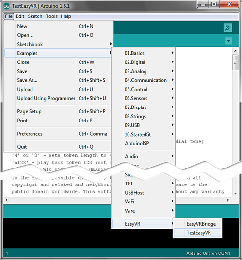
Figure 2 – Finding example sketches for the EasyVR
Test the Shield from the EasyVR Commander
- Select your Arduino board from Arduino IDE menu “Tools” > “Board” and the correct serial port (both choices must match the on-board USB port you have connected)
- Open and upload the example sketch “TestEasyVR” or “EasyVRBridge” from the Arduino IDE menu “File” > “Examples” > “EasyVR”
- Make sure the “Serial Monitor” window is not open in the Arduino IDE
- Open the EasyVR Commander and connect to the same serial port used by Arduino
When the EasyVR Commander is connected, you can also generate a template code for Arduino that will use the provided libraries (see EasyVR Arduino Library Documentation). All you need is to write actions for each recognized command.
Download custom data or Firmware update
- Follow the same steps for the EasyVR Commander above, but make sure to adjust the Mode Jumper settings for your main board (see table above) and that the PROG red LED is on
- While the EasyVR Commander is disconnected choose “Update Custom Data” from the “File” menu or “Update firmware” from the “Help” menu
