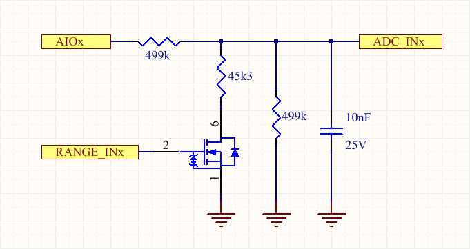
There are 4 analog input channels on the Main connector, that share the same external pin with digital channels. The MCU can select one of two external input ranges:
- Range = High (0 – 32 Volts)
- Range = Low (0 – 5 Volts)
Here below the simplified schematic of each analog channel:

Here is an example Arduino sketch that reads analog inputs AIO1 and AIO2 and prints out the measured voltage:
void setup() {
  // Open and wait serial terminal
  Serial.begin(115200);
  while (!Serial);
  // Configure analog input range
  pinMode(PIN_C_IN1_PD, OUTPUT);
  digitalWrite(PIN_C_IN1_PD, LOW);  // Range 0-5V
  pinMode(PIN_C_IN2_PD, OUTPUT);
  digitalWrite(PIN_C_IN2_PD, HIGH); // Range 0-32V
  // Set ADC resolution
  analogReadResolution(12);
}

void loop() {
  // Read analog channels and convert to Volts
  float vin1 = analogRead(AIN_EXT_IN1) * ANALOG_SCALE_LOW * ANALOG_VREF / 4095.0f;
  Serial.print("AIO1 (V): ");
  Serial.println(vin1);
  float vin2 = analogRead(AIN_EXT_IN2) * ANALOG_SCALE * ANALOG_VREF / 4095.0f;
  Serial.print("AIO2 (V): ");
  Serial.println(vin2);
  delay(1000);
}
The same example with Zerynth:
from fortebit.polaris import polaris

polaris.init()

while True:
    print("AIO1 (V):", polaris.readAnalogInputVoltage(0, LOW))
    print("AIO2 (V):", polaris.readAnalogInputVoltage(1, HIGH))
    sleep(1000)
