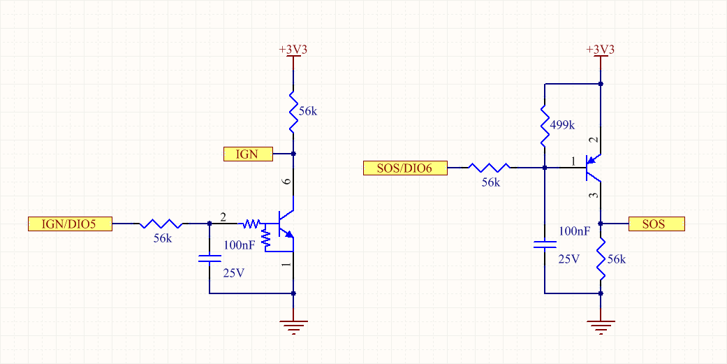
There are 2 dedicated digital inputs on the Main connector, that share the same external pin with digital output channels:
- Ignition (IGN) / Digital I/O 5 (DIO5)
- Emergency (SOS) / Digital I/O 6 (DIO6)
Here below the simplified schematics (ignition is active-high, while emergency is active-low):

Here is an example Arduino sketch that reads both digital inputs and displays their status:
void setup() {
  // Open and wait serial terminal
  Serial.begin(115200);
  while (!Serial);
  // Configure ignition detection
  pinMode(PIN_S_DETECT, INPUT);
  // Configure emergency button
  pinMode(PIN_S_BUTTON, INPUT);
}

void loop() {
  // Read ignition status
  Serial.print("Ignition (IGN): ");
  if (digitalRead(PIN_S_DETECT) == HIGH)
    Serial.println("OFF");
  else
    Serial.println("ON");
  // Read emergency status
  Serial.print("Emergency (SOS): ");
  if (digitalRead(PIN_S_BUTTON) == LOW)
    Serial.println("OFF");
  else
    Serial.println("ON");
  delay(1000);
}
The same example with Zerynth:
from fortebit.polaris import polaris

polaris.init()

while True:
    print("Ignition (IGN):", "ON" if polaris.getIgnitionStatus() else "OFF")
    print("Emergency (SOS):", "ON" if polaris.getEmergencyStatus() else "OFF")
    sleep(1000)
